Why EspHome – Evolution of the use of ESP8266 and ESP32 in home automation

As probably many of you, I followed an evolution in the way we approach the use of ESP modules (esp8266 and esp32)

Early Days

Custo project with Esp8266

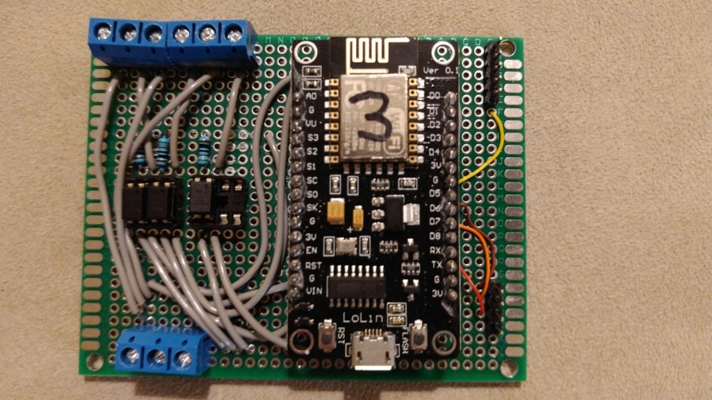
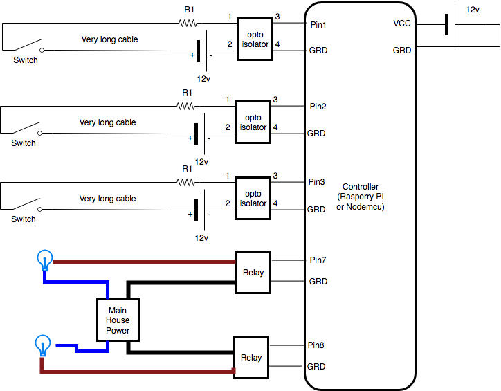
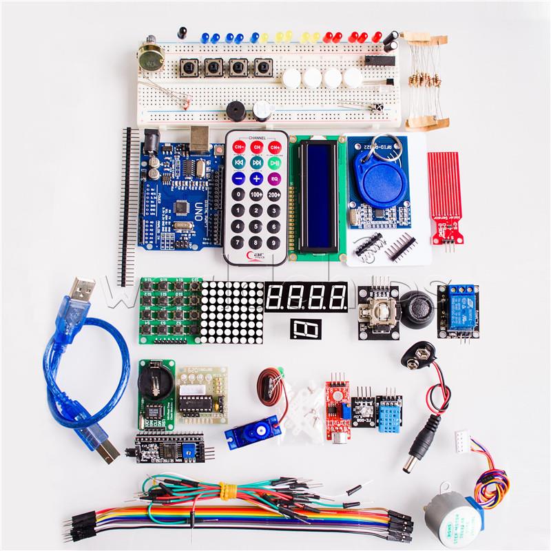
At the very beginning, it was 2016, I developed independent appliances based on these 2 modules esp8266 and esp32. I created my own remote-controlled switches and sensors, together with my own developed web application able to control them and collect data from them, such as a long-distance switch controller. I created lots of automation written in the firmware of esp8266 or esp32, integrating them with Google Home. Debugging was not so easy, the same collecting logs remotely. In everyday life there were multiple issues, such as usual big fighting with memory issues, finding the best way to connect external devices and sensors, general stability, the need to detach modules from the original location and connect the module to my PC to upload updates, etc. All these were annoying problems preventing me to implement a wider use of these solutions.

Ready to use commercial devices

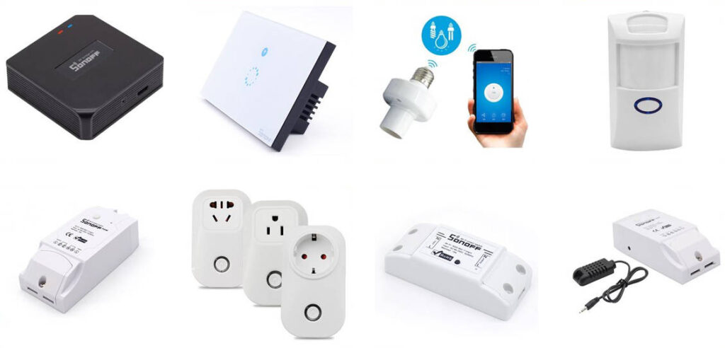
Some years later I realized I was able to find in the market very cheap commercial devices, ready to use, more or less with the same functionalities of the components I developed, quite reliable, compact, with an industrial level of engineering design. For sure they provided the main added value when they were able to work out of the box, even if it was possible to introduce small customization to make them be compliant with some custom requirements. So I decided it was time to stop spending time developing my own modules from the scratch using ESP8266 and ESP32.
As you know the main problem with these commercial modules was the fact each of them live in their own environment. Having components coming from different main families, such as Tuya, eWeLink, Philips, Shelly, and so on, I was not able to manage easily altogether.
You were able to deploy custom firmware to make them work altogether, but now every device was easy to be rooted with a custom firmware, the risk to brick these devices was high. Without any firmware customization, each of these families has its own management/automation software, mainly on mobile, so you create automation involving in the same moment components coming from different families was not easy and reliable.

Introducing Home Assistant

It was time to introduce an high-level governance for all devices in my home. So I installed Home Assistant, a wonderful software able to control a huge amount of different branded devices in a single environment. You can install it on a small dedicated device such as Raspbeddy or similar, or you can resurrect an old computer for this use (mine is running on a virtual machine on a 2008 laptop). After introducing Home Assistant I realized not all commercial devices are the same. In my case, I have a mix of Sonoff eWeLink, Tuya and Shelly devices, and I was quite disappointed by Sonoff devices because no integration, including the official one released recently, provide decent support for these devices: they are not seen by Home Assistant as devices, so you can not develop your own automation leveraging on the main feature available on Home Assistant.
I changed the custom software installed on my existing Esp8266 and Esp32 modules to interact with Home Assistant but, as decided before, I was not planning to use them in any additional functionality for the problem described at the very beginning, even I was missing the chance to have some very custom devices.

EspHome and the new renaissament

The next evolution, but it was a return to the past, was EspHome. If you had experiences with Esp8266 and Esp32, this is your natural evolution. It is a component for Home Assistant to allow you to set up, add components, control, and update wirelessly any Esp8266 and Esp32 project.
As the first step, you need to connect an Esp module to your computer and, using the Home Assistant web interface, enroll the module in Home Assistant platform. During this step, EspHome will deploy the basic firmware on the Esp module. From that moment any other debugging, configuration or updates to the module will be done via WiFi, without moving the module from where it is located.
You will be not asked to write any code, just to edit a configuration file where you will describe any other device (sensors, relays, buttons, less, etc) attached to your Esp module.
As you can see on the EspHome site, there are tons of components supported, so it will be really easy to create any kind of custom project.
Esp modules will make your connected components available to Home Assistant, then any other automation you will implement inside Home Assistant
Even I am an avid fan of EspHome, I need to admit you can not do 100% what you are able to do writing your home custom Esp firmware. The integration of any particular component is very well supported, it is really hard you will be able to find a component (sensor, switch led, etc) you will be not able to connect and make it available to Home Assistant. Maybe because of the event-driven model of Home Assistant automation, you will be not able to reproduce some behaviors you need, but they will be really corner cases.
So I dismissed any custom self-developed firmware from Esp8266 or Esp32 around my house and I integrated them with Home Assistant through EspHome.

Projects with Esp modules and EspHome

These are for the moment the implemented solutions:
– Spiral staircase lights, with presence and light sensor
– Box to switch off lights when children left the room
– Multiple temperature sensors around the house

Remotelight – step 4 – Hardware

In our example we will have a room with 2 independent lights, one controlled by 2 switches, the other controlled by a single switch.

We will use Nodemcu pin 1, 2, 5 to read switches and pin 6 and 7 to pilot the relays. This is the general design:

We have 3 possible choices for assembling our project:
– Experimental bread boards: very easy to use, not stable because connections are “temporary”, very easy to change, usually the result is often a little messy. No need of solder.
– Prototype boars, Tinned Universal experimental boards: practical, you need a little of soldering experience, stable result, flexible in case of changes
– printed circuits: you need to design in advance non changes allowed, expensive, soldering experience needed, clean result

We decided to use an experimental board.

What you need:


RemoteLight – step 3 – the circuit

As described before in the desing of our project, we need a 12v circuit for the switches while we our pins in the GPIO works with 3.3v or 5v. To separate this 2 circuits we will use a Opto Isolator

What is an opto isolator?

It is a small component with 4 pins, 2 work in input and 2 in output.
The effect is when the current is passing from pin1 to pin2, current is allowed to pass from pin3 to pin4, when there is not current passing between the pin 1 and 2, current can not pass frompin3 to pin4.
Here you can see how it works.

There is a led connected to pin1(+) and pin2(-), so when there is current passing there is light emitted by the led. This light arrives to the sensor (phototransistor) that like a switch allows current to move from pin3(+) to pin4(-). It is not a real switch closing the circuit, it is always closed. Pay attention that, as I remember, current from pin4 to pin3 is always allowed, so in case you invert polarization, it does not work, current always goes through.

As you can see there is a total isolation between the circuit on the left and the one on the right, they can not damage each other even in case of physical failures. It looks like a small IC

Lets start to design how we want to use it:

There is a 12v power supply to provide power to the opto isolator circuit and make possible to have a very very long cable between our controller and the switch. To protect the led inside the opto isolator we need a resistor R1.
We will use pinX to understand if the Switch is close or not, when closed the pinX is connected to ground.

On the other side, the application inside the controller can give power to the pinY. This will give the signal to the relay to close the circuit and connect the main house power to the light, turning it on.

The 12v power supply will be used for
– the opto isolator circuit
– to provide power to the Controller
– to provide power to the relay, because even the relay need power: what is coming from the controller is used only as signal then there is the need of electric power to run the internal magnetic switch to  control mail 125/220v switch.

Let’s speak about the components more in deep.

As Opto Isolator we took a PS2501 (20pieces x 1.28$), it is one of the most common, here you can find all detailed specs: ps2501.pdf
From this document we can see the led works with a maximum  80mA (40mA are good enough) and a forward voltage of 1.15v. Using 12v to power it, the suggested resistor is 135 Ohm. I was more conservative, considering lower mA and a power supply less stable, so I choose a 510 Ohm. From this point of view these components are really flexible, use any resistor from 150 to 600 Ohm and it works fine. I have tested with cable till 10m with 510 Ohm without any problem, maybe in case of a much longer cable you can reduce the resistor.

About the Relays, due to our configuration I suggest to use a relay module with optical coupling isolation working with 12v because we have 12v available in our circuit so we do not need other sources.
They usually have 4 pins, 2 for the signal and 2 for the power needed by the relay to activate its magnetic component and pilot the internal switch.
if they is a common GRD for both signal and Vcc, there will be only 3 pins.

As controller we will use Esp8266 wifi soc  commonly named Nodemcu. It is small, very cheap, powerful board with Wifi integrated capabilities.
Nodemcu is the opensource firmware available for this small board, even often this name is used to define the board itself.
With a single board of this type we will be able to control 3-4 switch and 2-3 relays, thats because there are few pins available in the GPIO and many of these are reserved. Node MCU can be powere with any voltage from 5v to 24v, so it is perfect for our design where we will have 12v available.


RemoteLight – step 2 – from theory to practice

Step 2 of our project RemoteLight:

We want to build up our home automation with these requirement.

What kind of controller can we use?
We have 2 possible choices to have a low cost controller:
Raspberry PI/Banana PI/Orange PI board: from 15$ to 50$
A full operative system, with all programming languages available, lots of tools to debug all problems, may be too much powerful and complex for our small scope, but with all its debug tools, it can be very useful to make experiments.


ESP8266 Nodemcu board: 3$
Simple, able to do only few task, only Lua and C programming languages, small memory so only small code can run. But it is has anything we need.
Pay attention it is not so powerful, so for example the WIFI must have a good signal otherwise this micro board can suffer trying to connect to your wifi.

As we will see later, the work to do around these boards is quite the same, so you can use our suggestions for both boards. With a RasberryPI or similar board you can probably control more switches and lights with one board but, due to cabling constraint, it is not simple to manage all lights from a centralized location (this means having all cables starting from the same point and make them arriving to the finel position all around the house, that is usually not very simple) . This is one of the reason why at the end, as you will see, our choice was multiple Nodemcu boards spread around the house near the switches and lights it needs to control.

Let’s see how these boards work for our purpose.

All these boards are provided with a GPIO (General Purpose Input/Output) connection, made of multiple pins. Some of these pins can be read by a simple code inside the board, to ask if the pin is connected or not to the “ground” (specific pin marked as GRD). This way of using pins is called input mode.
So you can take a switch, even a big wall switch normally used with 125v or 220v, connect one wire to the pin, one to the ground, and with a simple code you can understand if the switch is opened (circuit interrupted, no current passing through the switch) or closed (circuit closed, the current pass through the switch).
Great!!! we achieved the first functionality of our controller. This is the way we can read if a switch is off or on.

Then you can use another pin in output mode, so you can send out a signal and this signal can, for example,  turn on a led as it can turn on a relay, making the high voltage electricity reach your light.
And this is the second part of our controller. We can pilot a switch to turn on/off a real 125/220v lamp.

Here you can see a simple experiment, where a normal wall switch, in this case, a Bticino switch, is connected to the GPIO of a OrangePI, then a led was connected to a different pin and with a very simple python script every second a check is done to the switch, if the status of the switch is changed, the led status is inverted.

Is everything clear? Ready to implement this theory in your home automation?

Unluckily things are not always so simple. The pin of the GPIO of your board generates a very low tension, 3.3v or 5v depending on the model of the board you choose. Perfect if the distance between your board and the switch is a few centimeters (as in the previous video) or a few meters, but in real life, the cable between the controller and the switch can be longer, maybe  10-15 meters long or more. Due to this the resistance of the cable can influence the circuit, reducing the ability for the current to return to the board to show the switch is closed. The signal gets lost or is unstable, so it is not very clear if the circuit is open or closed. If you have a very very long distance from the switch to the board, it is better to build a parallel circuit with a higher voltage, at least 12v or 24v, so the effect of the resistance of the long cable is compensated. For the same reason to move electrical power from production plants to towns, 125v or 220v are not enough, the voltage is transformed to 30.000v (small lines) or 1.000.000v and then back to 220v at the end of the journey.
But such high voltages (12v or 24v) can not arrive in contact with our board, they would burn your board designed to work with 5v maximum.
How to solve the problem?!!? The magic optoisolator
Let’s go to the next page

RemoteLight – step 1 – requirements and general architecture

Let’s start with our project: Remote light

Mission:
We want to build up a system to control, with a web interface, all the lights of our house, with a small impact in terms of user experience (everything should work as before) and in terms of cost.

Requirements:
– we want to be able to control from our PC/mobile device every single light of our home, if they are on or off and switch them on/off from our device.
– we do not want to change any wall switch in our home, we want to use the same in use in this moment
– we do not want to change any light inside our home. Any lump or bulb should be involved without changing them.
– for people not directly interested in home automation (like my wife) everything should work in the old plain way, the same user experience as usual. He should not even be able to understand something has changed behind the curtain.
– everything should work without Internet, no external dependencies
– in case the wifi in the home is down, everything should work as usual: when I operate on the wall switch, light should turn on or off without any problem. Obviously it will be impossible to control lights from your pc or mobile.
– if in the house we have 2 switches controlling a single light, this behavior must be replicated as is
– we do not want to use a close standard or a specific vendor line of products

Nothing special, any serious Home automation system provides this kind of features. Usually the cheap components, easy installation with no configuration, are not able to provide you there features, due to strong dependencies from external infrastructures.

How can we achieve these result?
The main idea is to have a small controller able to understand the status of our wall switches and to control the light.
In this example we will have 2 wall switches controlling a single light. A classical configuration presents in all houses with 2 diverters (divA and divB) and a light.

Now image you introduce a very small “controller” able to understand if one of the 2 switches changes the status (from on to off and vice versa) on one side, on the other side  is able to turn the light on or off through a small relay.
You achieve your target to use, through a complex controller, standard light bulbs (led or whatever) and the same wall switches as before.
What is missing is only a little of logic:
when one of the switch change its status, the controller has to invert the status of the light (from on to off, from off to on). Because this small controller is attached to our wifi, we can even ask directly to the controller the status of the light and change it. So the message the controller is able to understand is only “change the status of the light” and this can happen due to a wall switch changing its status or with a remote wifi command.

The relation between light and switches becomes only login, no physical direct connections among them.
This will allows you to have a single light controlled by 3-4-5 different switches placed around the room, readdy difficult to have with a normal electric circuit.

Because we are thinking about a very small controller, with limited capabilities (3-4 switch, 1-2 lights each) we can think to have one for room, so we can plan to have an application to coordinate all of them. If you want a single command to switch off all lights in your house before going out, you need this coordination.

Let’s see the controller we can use and how

Where to buy stuff

First of all you will need to buy what we suggest for our product. They are not very common stuff, like a charger for mobile phone, you can buy in any store.
But they are quite common you can find easily on Amazon, eBay or AliExpress.

Where to buy these stuff depends how long you are available to wait.
A Chinese site like AliExpress provides you the best prices, but often you need to wait for one month to have your stuff at home. Using Amazon you have a better time to receive stuffs, but the price is not so cheap as you can find in AliExpress. For eBay it is variable, depending on the reseller.

We will suggest possible packages or versions so it will be easier for you to find the exact product on the market

Aliexpress: http://www.aliexpress.com
Amazon: http://www.amazon.com (or take a look to your local version)
eBay: http://www.ebay.com (or take a look to your local version)